Update on Custom Hardware Seizure Detector

I have been working on the custom hardware seizure detector for a couple of weeks.    The code and schematics are on Github. 

Progress to date:

  • We can write firmware for the ESP32 microcontroller using the FreeRTOS framework 🙂
  • Access the I2C bus to talk to external sensors (such as the ADXL345 accelerometer).
  • Wire multiple devices to the I2C bus (I have a heart rate and blood oxygen saturation sensor, and a small display on it too).
  • Proved that we can communicate with both the accelerometer and display modules.

In Progress at the moment:

  • Modifying the I2C bus access code to make sure that only one process accesses the bus at a time, otherwise things will go horribly wrong when we try to use multiple devices, all managed by their own software process (task in FreeRTOS speak).
  • Ordered the main parts for the prototype (I am feeling lucky that I will get the ESP32 based system power consumption down far enough to complete the Proof-of-Concept.

The current proof-of-concept hardware is a rats nest of interconnected bought-in modules – not pretty!

Proof-of-Concept OSDWatch Hardware (ESP32 based)

Work to Do to Complete Proof-of-Concept

  • Complete the I2C bus access framework and routines to access:
    • ADXL345 Accelerimater
    • MAX300102 Heart Rate and Saturation module
    • OLED Display
  • Write code to send data to parent device over bluetooth periodically.
  • Check Power Consumption
    • Switch off the un-used ESP32 peripherals (e.g. WIFI) to reduce power consumption to give us at least 12 hours from a small LiPo battery.

Work to do for Prototype

  • Design a custom PCB to hold the main components (rather than using bought in modules that are wired together) – necessary to get it down to wrist watch size.
  • Get a small number of PCBs manufactured (there seem to be a few companies that do this cheaply in China).
  • Design a watch case, and manufacture a few using 3D printing.
  • Populate PCBs with components and solder them.
  • Test using proof-of-concept code.
  • Extend the OpenSeizureDetector android app to have a new Data Source which will be the custom OSD watch
  • Update the firmware to communicate with the Android App.


Custom Hardware Seizure Detector

We have made some progress with a feasibility study into running OpenSeizureDetector on very low cost hardware – I have started a page Custom Hardware Seizure Detector that I will update as we develop it.

It would be really good to know if people are interested in this – please either get in touch with graham@openseizuredetector.org.uk or our facebook page http://facebook.com/openseizuredetector.

Potential Custom Seizure Detector Hardware?

With Pebble watches not being available any more, and Android Wear devices being very expensive, I am still wondering about an alternative seizure detector hardware platform.

I have heard about ESP8266 modules – they are small microcontrollers with built in wifi capability.    Although most people connect them to another microcontroller, it is possible to write your own software to run directly on it so I am wondering if it may be possible to make a seizure detector watch with them – It would need an ESP8266 module, an accelerometer chip and a LiPo battery, and put it in a 3D printed case.

I have just got an ESP8266 module with a built in USB interface.  This is a bit on the big side, but about the same size as a Pebble Time, so not out of the question (top image on right)
I have also got a few smaller modules that do not have a USB interface, so will take a bit more programming, but they are a lot smaller (bottom image on right)

The most surprising thing is the cost – the big one with extra hardware was just over £5, but the small ones are less than £2 each – it is hard to believe anyone can manufacture things and ship them from China for that price….

I have set up the compiler toolchain from https://github.com/pfalcon/esp-open-sdk, and obtained the tools to interact with the boards from https://github.com/espressif/esptool, and finally obtained some example programmes from https://github.com/esp8266/source-code-examples.git, which includes a ‘blink’ example.

After a bit of faffing to get the Makefile to work with my new cross compiler, ‘make’ will compile the programme, and ‘make flash’ will write it to the board.

After which – the on-board LED flashes on and off every second – success – the Microcontroller equivalent of ‘Hello World!’.

Next steps are:

  • Connect an accelerometer chip  to the board, using the SPI or I2C interface and try to read data from it (like I did using an Arduino back in 2013 – Soldering onto Surface Mount ICs).
  • Port the Pebble_SD seizure detector algorithm to the board to see if it will fit.
  • Get it to act as an OpenSeizureDetector network data source so that other devices can connect to it to detect alarms etc.
  • See if we can get the power consumption down enough that running it off a watch battery is feasible.
  • If it seems feasible, re-commission my 3D printer and try to make a case.
  • Think about adding an optical heart rate and blood saturation measurement to it.

The video below is not exciting, but it proves we can at least run a programme on one of these tiny (and very cheap) boards.


Soldering onto Surface Mount ICs

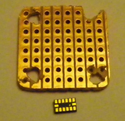
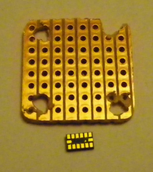
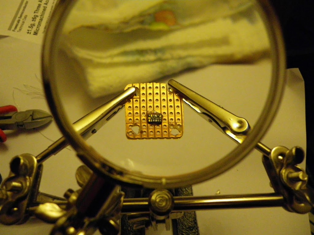
I recently bought an accelerometer IC to use on my epileptic seizure detector project.  It is a tiny surface mount device as you can see below.

I gave a lot of thought to how to connect wires to it.  I did consider conductive glue, but it would be difficult to hold them all still for long enough for it to set, so I went back to solder.  This is how I did it…
1.  Mount the IC onto stripboard using apoxy adhesive:
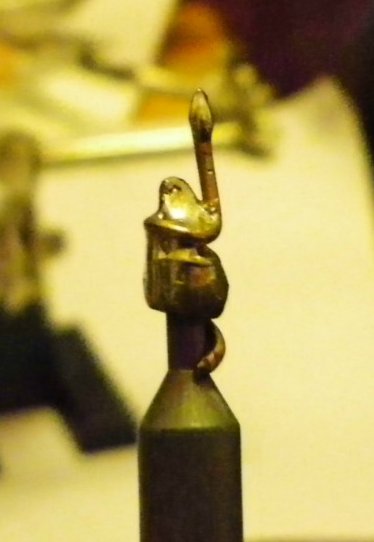
2.  While the glue is setting, modify the soldering iron by wrapping some 1mm2 copper wire around the tip to give a very fine tip.  Use solder to increase the heat transfer between the wire and the tip:
3.  Tin the solder pads on the IC, using some very fine solder (I got some 32swg solder off ebay).
4.  Obtain some very fine copper wire (I disassembled some cheap alarm flexible cable, and used strands from that).
5.  Hold a strand of wire onto a solder pad, and touch it with the soldering iron to melt the solder and create the joint.
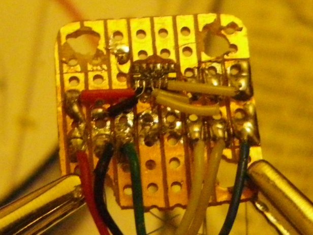
6.  Repeat for all connections:
7.  Route the fine wires to the copper tracks, and solder on.  I used the insulation from the original alarm  cable to prevent short circuits:
Fiddly, and not very neat, but it worked for me – it is being used in my prototype epileptic seizure detector.